


Request our Free Info
Pack & Stickers
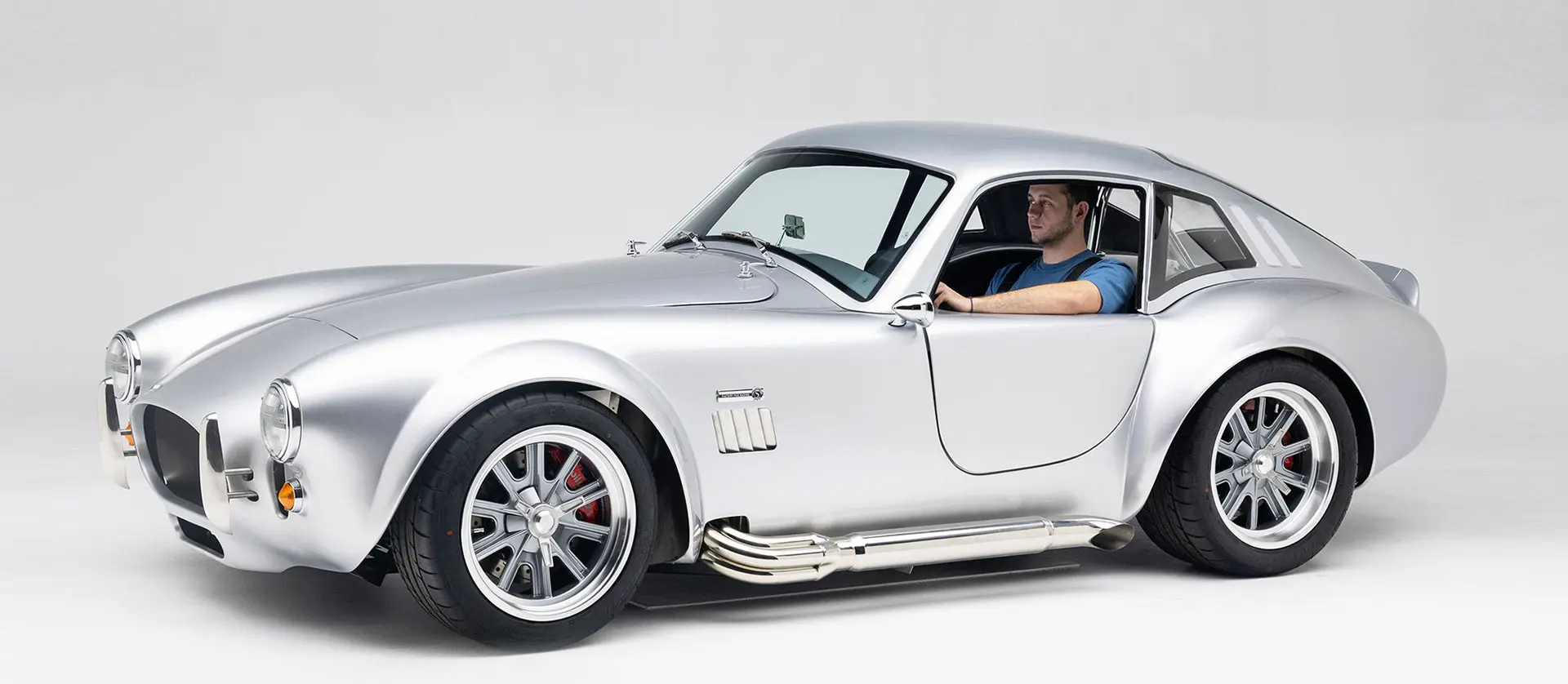
The Mk5: Revolution
Meets Evolution
金刚国际GTM超级跑车 | 双门跑车底盘设计
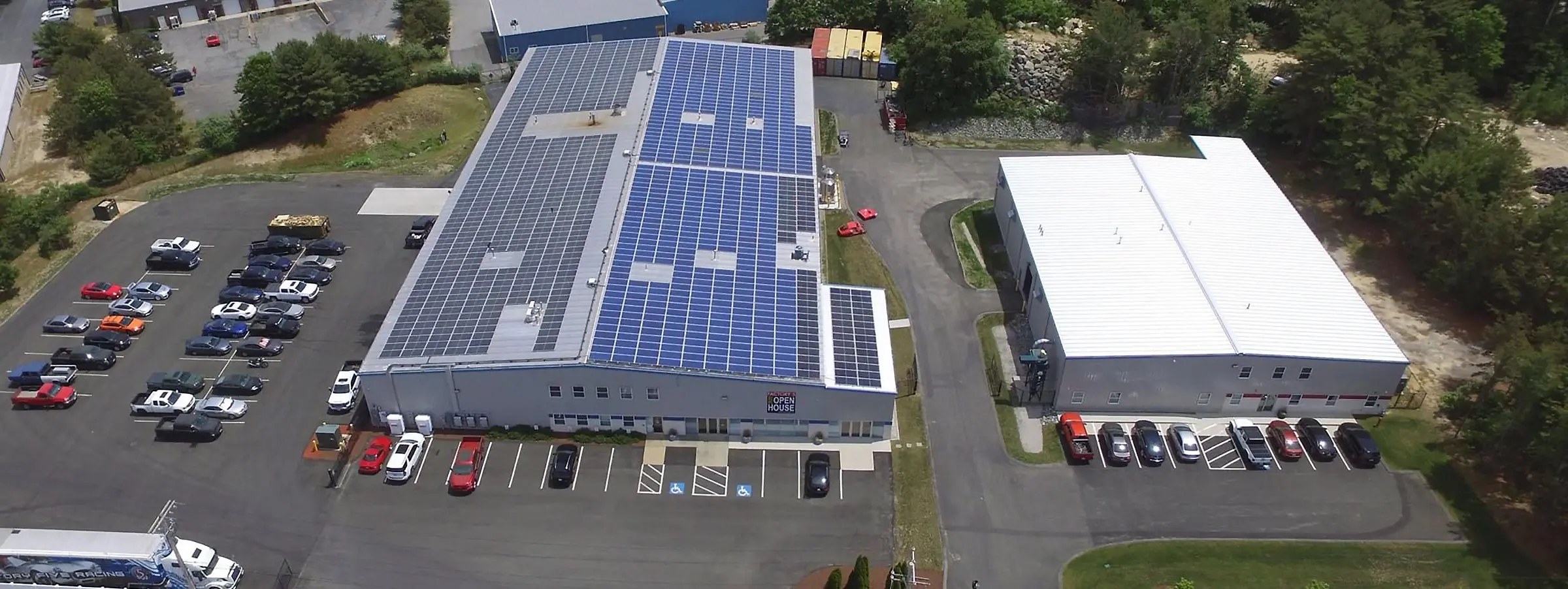
金刚国际从一家小型车库里的初创企业发展成为全球最大的“DIY”汽车零部件套件制造商。我们拥有约40名全职员工,公司位于马萨诸塞州韦勒姆(波士顿以南约一小时车程)。我们的产品全部在美国本土生产,这里是美国制造业的发源地——新英格兰的中心地带。
汽车零部件套件制造商

Christmas Came a Few Days Early for Hunter L.!
The holiday week started off this morning with a family picking up their new Factory Five! Carly D. surprised Hunter…
Read More
Carl N. Graduates his Gen 3 Coupe, F5R1000117DC!
Congratulations to customer Carl N. from Connecticut on graduating his 65型双门轿跑车 build! Carl picked-up his Coupe in Fall…
Read More
Kie H. Hits Two Big Milestones During his Mk4 Build!
Our customers always make our day when they send a message sharing their build progress, their stories, and how much…
Read More
The Bello’s Test Drive Their ’33 高性能Hot Rod底盘
Anthony and Evelyn Bellow started dreaming of building a Factory Five ’33 高性能Hot Rod底盘 in 2009. They both were serving…
Read More
Bill E. Graduates his 金刚GTM敞篷跑车!
“This car is giving me such joy and fun!” – Bill E. Congratulations to customer Bill from Woodway, TX on…
Read More
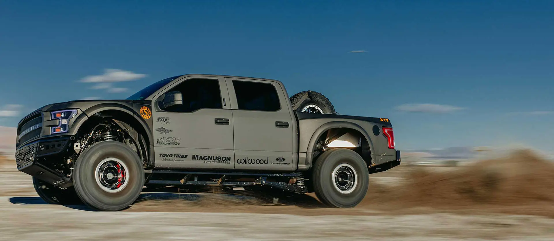
Joey Logano Sends His XTF for Town1 Ground Breaking!
3X NASCAR Champion, Joey Logano sent his XTF off a dirt jump to celebrate the Town1 Ground Breaking in Huntersville,…
Read More
Factory Five Operations Update!
The big SEMA show is behind us, and as we approach the final month of the year, the Operations crew…
Read More
Picture of the Month: Mark G.’s 65型双门轿跑车 at Road Atlanta
This month’s featured photo from The Factory Five Forum comes from Mark Gray, capturing his Factory Five 65型双门轿跑车…
Read More
A Weekend at the Factory Five Build School
The Factory Five Build School is a hands-on experience that gives customers the knowledge and confidence to tackle their own…
Read More
Joey Logano’s Most FUN Car is his Hot Rod Truck!
3X NASCAR Champion, Joey Logano calls it his most FUN car of all time…it’s his Factory Five ’35 Hot Rod…
Read More金刚国际敞篷跑车
Some Evolution, More Revolution
该设计的每一次迭代都让汽车更快、更强、更安全,也更容易制造。2010年我们推出第四代车型时,正如我之前所说,这是“最后一次尝试”,因此第四代车型的改进幅度是当时所有版本中最显著的。.
随着金刚国际迎来公司成立30周年纪念,我们即将进入全新一代 Roadster——Mk5的量产阶段。许多改动具有深刻的革命性,使整车设计达到前所未有的高度;而有些改动则是渐进式的,主要是对现有零部件和设计进行优化与提升。
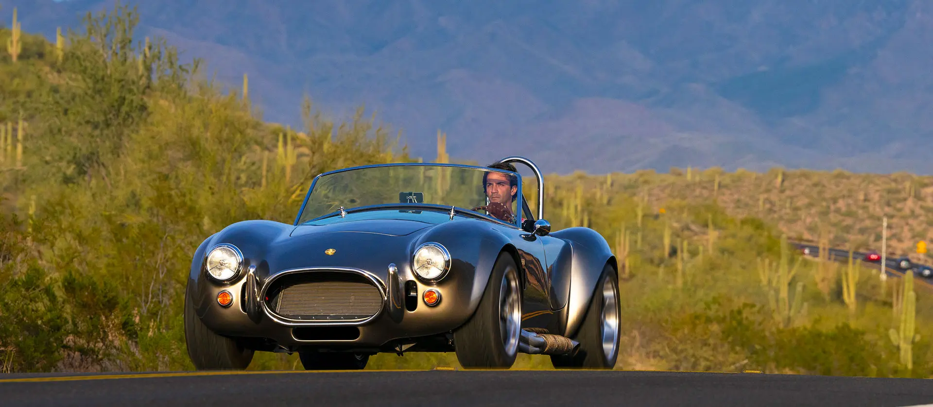
金刚GTM敞篷跑车
The Factory Five 金刚GTM敞篷跑车 is the world's best-selling, best-engineered, and best-performing replica of all time.
There is no better way to honor a legacy than to continue it. The 金刚GTM敞篷跑车 is designed to accurately reproduce the looks of the legendary 427 Cobra*, keeping its essence intact, while using modern technology, parts, and materials to improve performance, reliability, and comfort.
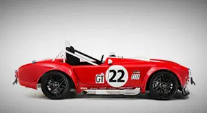
28289赛车版敞篷跑车
Period Correct. Period.
The Factory Five 28289赛车版敞篷跑车 is a gentleman’s racer. It is smaller, more precise, and is the saber to the Mk4’s broadsword. For sure, the car appeals to a smaller group than the best-selling Mk4, but it has a passionate following.
MK4-R Challenge Car
Competition Only
he Mk4-R Challenge car is the competition version of our best selling 金刚GTM敞篷跑车. The car takes the 金刚GTM敞篷跑车 to a more serious competition level and is engineered to be used in wheel-to-wheel road racing,
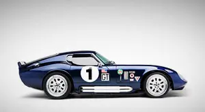
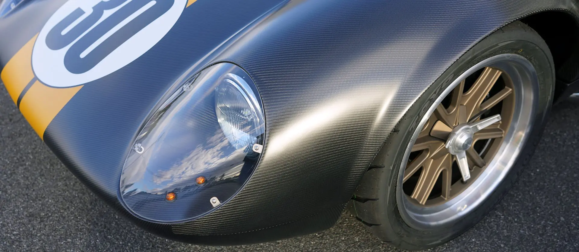
65型双门轿跑车
汽车历史上最独特、最惊艳的造型之一
Designed to be an accurate replica of the original 1965 World Championship Coupe, the 65型双门轿跑车 was made to capture the look and feel of the original 200 mph GT cars, but also use today’s engineering to make it more reliable and comfortable.
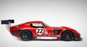
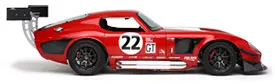
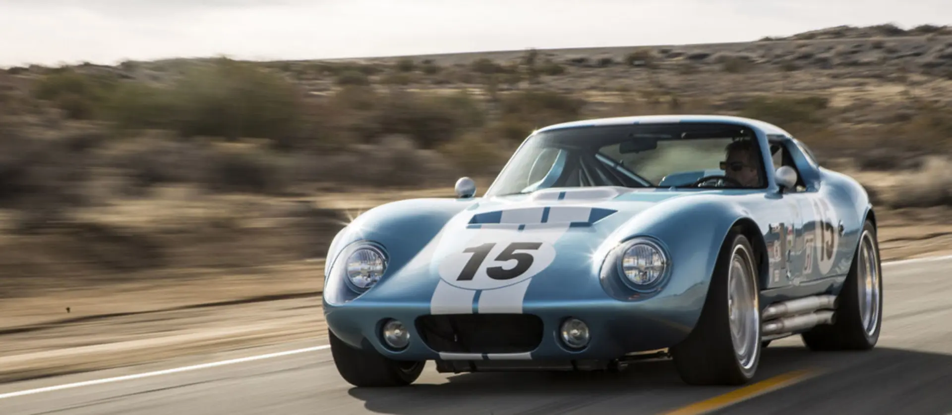
65型双门轿跑车-R
The Race Version of the Gen 3 Coupe
The 65型双门轿跑车-R is based on the complete kit version of the 65型双门轿跑车, but made for professional competition. The largest difference between the Gen 3 Coupe and the Gen 3 Coupe-R is that the Coupe-R comes with a competition cage chassis (powdercoated in white like all Factory Five competition version chassis).
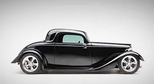
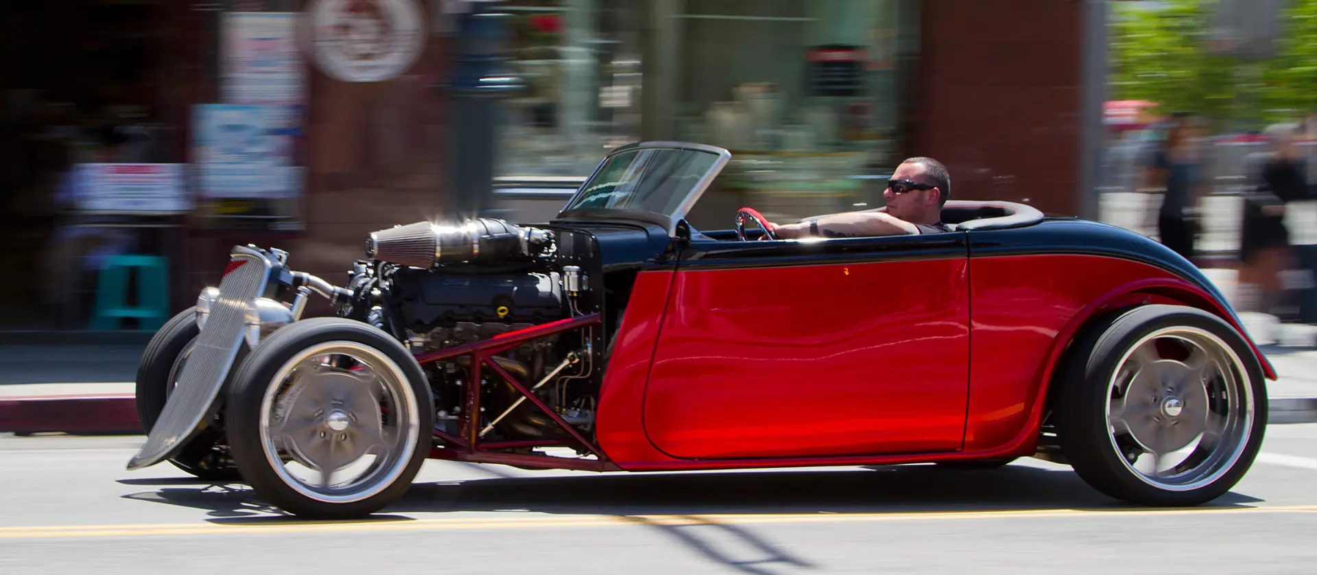
'33 高性能Hot Rod底盘
The Award-Winning Factory Five '33 高性能Hot Rod底盘
A beautiful machine whose handling and performance match its good looks, our '33 高性能Hot Rod底盘 has garnered a slew of awards and industry recognition, redefining what a modern hot rod build can be.
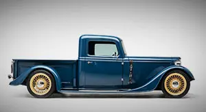
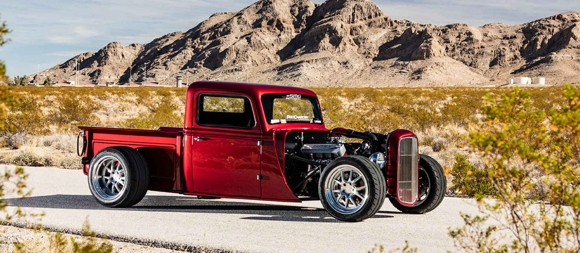
金刚国际'35 Hot Rod
Period-Correct Wicked Fast '35 Truck!
全新 Factory Five '35 Hot Rod 皮卡 延续了 Factory Five 一贯闻名的操控性与性能,同时展现出酷炫、符合年代感的巡航风格。配备有独特设计的座椅、可用的5英尺货箱、传统车门和驾驶舱。外观复古经典,整备质量仅 2,380磅(约1,079公斤),速度极快,让人惊叹。
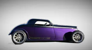
Speedstar
Ridler Award-Winning Design
The award-winning Speedstar body now drives as good as it looks with the proven Factory Five performance Hot Rod chassis underneath! We bought Rat’s Glass Bodies, and this all-new shape is the first result of that acquisition.
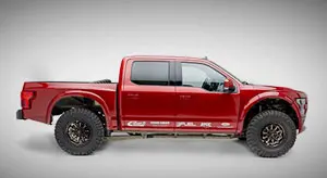
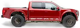
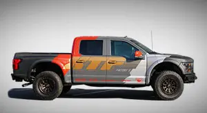
XTF Pre-Runner Truck
A "Build-It-Yourself" Raptor on Steroids
Introducing the Factory Five XTF Pre-Runner Truck kit! Take your 2015-2020 Ford F-150 and turn it into an off-road beast with our full tubular chassis, long travel suspension and super wide 90” complete body package! This new kit is the ULTIMATE upgrade for your F-150 Truck!
用 Blueprint 发动机亲手打造你的专属高性能跑车
Brand-new, reasonably priced, high-performance, drop-in engines that are dyno-tested with full warranty and ready to run and a perfect matched for Factory Five kits.
加入金刚国际社区论坛,和车迷一起交流
You can join this community whether you have a car or not. The Factory Five Forum is a great place to start talking to other FFR guys. Our Facebook and Twitter page is used to post fun news about the guys here and customers.